Waste-to-Energy Plants Are Our Path to a Sustainable Future.
Australia’s total waste generation reached 75.6
million tonnes in 2022–23, or about 2.88 tonnes per person, a 20% increase over
the past 15 years that outpaces population (+25 %) and GDP (+38%) growth.
Despite achieving a 63% recycling rate and an
additional 3% energy recovery (for a combined 66% resource recovery), roughly
34% of all waste still goes to landfill, creating environmental, economic and
logistical pressures.
Key Waste Streams.
Household waste: 12.4 million tonnes annually
(2018–19)
Commercial & industrial waste: ~16.9 million
tonnes annually (2021–22)
Construction & demolition waste: 25.1 million
tonnes (2020–21), around 1 tonne per person
Food waste: approximately 7.6 million tonnes per
year, costing households up to AUD 2,500 each
E-waste: about 0.8 million tonnes generated
annually and projected to grow with device turnover
Plastic waste: 2.5 million tonnes each year, with
Australia leading the world in per-capita single-use plastic consumption
Landfill Capacity and Environmental Impact.
Australia operates over 1,200 landfill sites
nationally. Major cities like Sydney and Melbourne could exhaust existing
landfill space by the early 2030s, driven by urban growth and limited site
availability.
Landfills remain a key source of methane emissions
and can leach contaminants into soil and groundwater. Reducing the volume of
waste sent to landfill is critical for cutting greenhouse gases and protecting
water quality.
Policy and Market Evolution.
The National Waste Policy Action Plan sets an
ambitious target of 80 percent resource recovery by 2030. Recent export bans on
key recyclables—alongside global restrictions like China’s National Sword
policy—have pushed Australia to expand domestic processing capacity and seek
innovative waste solutions.
What Are
Waste-To-Energy Plants?
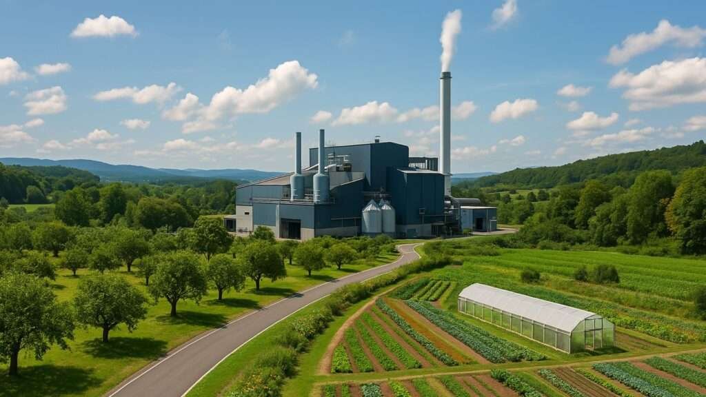
A waste-to-energy (WtE) facility is best described
as a purpose-built industrial complex where non-recyclable municipal and
commercial wastes are converted into usable energy under tightly controlled,
environmentally safe conditions.
Key Architectural and Process Zones.
Reception
& Pre-Processing Hall: An enclosed, odour-controlled
building with tipping pits and conveyors, where incoming waste is unloaded,
sorted (metals removed), and homogenized before combustion.
Combustion
& Boiler Hall: A high-temperature furnace or
grate system housed within a steel-framed, fire-protected structure. Waste is
burned at 750–1,100 °C, and the resulting heat is transferred through water-tube
boiler panels to generate high-pressure steam.
Turbine
& Generator Building: Adjoined to the boiler hall,
this sound-insulated hall contains turbines and generators that convert steam
energy into electricity. Condensers and feed-water equipment complete the steam
cycle.
Flue-Gas
Treatment Wing: A multi-stage treatment train—baghouse
filters or electrostatic precipitators, acid-gas scrubbers, NOx reduction
reactors, and activated-carbon injectors—enclosed in a separate chamber or
mezzanine above the boiler. Continuous emissions monitors feed data back to a
central control room.
Ash
Handling & Resource Recovery Zone: Bottom
ash conveyors, magnetic and eddy-current separators, and storage silos are
located adjacent to the boiler hall. Fly ash and scrubber sludge are collected
in sealed skips or silos for safe disposal or reuse in construction materials.
Control
Room & Services: A climate-controlled operations
center housing distributed control systems (DCS), SCADA panels, and real-time
emissions displays. Nearby workshops, maintenance bays, electrical substations,
and administrative offices support plant operations.
Stack
& Utilities: A tall chimney (often >80 m) for
clean-air dispersion, plus service buildings for water treatment, backup
generators, and chemical storage (e.g., lime for scrubbing).
Design Drivers.
Process
Flow Efficiency Buildings are arranged linearly, from
waste reception to energy generation to emissions control, to minimize material
handling and energy loss.
Environmental
Safeguards Enclosed halls, negative-pressure ventilation,
multi-barrier emissions controls, and on-site water treatment ensure compliance
with stringent air, water, and noise standards.
Safety
& Maintenance Fire-resistant cladding,
redundant safety systems (sprinklers, deluge), overhead cranes, catwalks, and
easy access to key components streamline maintenance and emergency response.
Community
Integration Thoughtful landscaping, visual screening of
stacks, and public-access viewing galleries or visitor centers help demystify
operations and build social license.
Scalability
& Flexibility Modular grate sections, boiler
panels, and gas-cleaning modules allow capacity expansions and adaptations to
changing waste streams or stricter regulations.
In a
nutshell:
A WtE facility reads like a compact city of
ultra-robust halls, each tailored around a critical thermal-chemical process designed
to turn “rubbish” into reliable power and recover valuable materials, all while
safeguarding people and the environment.
1. Waste Reception and Pre-Processing.
Waste arrives by truck into an enclosed tipping
hall, where overhead cranes or hydraulic grabs transfer it onto a feed
conveyor.
Negative-pressure ventilation captures odours and dust, routing air back to the flue-gas scrubber to prevent fugitive emissions. Automated metal detectors and magnets remove large ferrous objects before waste is fed to a hopper or bunker for continuous combustion feed.
Key components:
Tipping pit with slewing crane.
Magnetic separators for metals.
Bunker with agitators for homogenization.
Negative-pressure ventilation system.
2. Combustion and Thermal Treatment.
The core of the plant is a high-temperature
furnace. Mixed waste is fed onto a moving grate (or into a fluidised-bed
reactor), where controlled air injection ensures complete oxidation at
750–1,100 °C.
Moving grates shift waste through drying, ignition, and burnout zones in sequence, reducing volume by up to 90 percent and converting chemical energy to heat in the boiler’s water-tube walls.
Key considerations:
Grate design (step, reciprocating or traveling
grate).
Zoned air staging for low NOx formation.
Refractory linings to protect furnace shell.
3. Boiler and Steam Cycle.
Heat from combustion passes through a bank of
water-tube boiler panels. Water is pressurised, superheated, then directed to
steam turbines.
A typical plant generates 500–600 kWh per tonne of waste burned. After expansion in the turbine, steam is condensed and returned via feedwater heaters, economizers, and superheaters to maximise thermal efficiency(20–30% net electrical)
Process Flow:
Combustion heat → Boiler
Steam generation → Turbine
Electricity via generator
Condensation and recirculation
4. Flue-Gas Treatment and Emissions Control.
Flue gases exit the boiler at 200–300 °C and pass
through multi-stage cleaning:
Particulate removal:
Electrostatic precipitator or baghouse filters capture dust and fly ash (96–99
percent efficiency).
Acid-gas scrubbing:
Lime or sodium hydroxide injection neutralises HCl, HF and SO₂, producing inert
salts or gypsum.
NOx reduction:
Selective catalytic reduction (SCR) with ammonia or urea achieves >80
percent NOx removal.
Activated carbon injection: Adsorbs heavy metals (mercury, dioxins) before final polishing and stack discharge.
Continuous emissions monitoring systems ensure
compliance with stringent air-quality standards and provide real-time feedback
to control systems.
5. Ash Handling and Residue Management.
Two categories of ash are generated:
Bottom ash (10 percent by volume):
Collected beneath the grate, cooled and conveyed for metal recovery via magnets
and eddy-current separators. Remaining inert aggregate can be used in concrete,
road base, or backfill.
Fly ash and scrubber sludge: Captured in baghouses and wet scrubbers, forming fine particulates and gypsum by-products. Often stabilised and landfilled or used in cement clinker substitution after testing for leachability.
By‐product recovery:
Recycled ferrous/non-ferrous metals (~5 percent of
input mass)
Ash aggregates with pozzolanic properties
6. Building and Structural Considerations.
The plant sits on reinforced foundations designed
for heavy static and dynamic loads. Key structural elements include:
Steel‐framed boiler hall with high‐temperature
refractory cladding
Chimney stack sized for dispersion height (often
>80 m)
Service corridors, maintenance gantries and crane
rails
Firewater deluge systems and bunding for secondary
containment.
Layout optimises material flow from waste
reception through combustion to ash handling and flue-gas cleaning.
7. Control Systems and Automation.
Modern WtE plants employ distributed control
systems (DCS) for:
Feed rate modulation based on calorific value
sensors.
Combustion air staging and flue-gas recirculation.
Boiler pressure and temperature control loops.
Emissions monitoring and corrective dosing.
Remote diagnostics and predictive maintenance via
SCADA interfaces.
8. End Products and By-Products.
Electricity and/or heat:
Base-load power for the grid or district heating networks.
Bottom ash aggregates:
Road base, concrete additives or hydraulic binders.
Recovered metals:
Sold to foundries or steelworks.
Gypsum and salts:
From acid-gas neutralisation, used in construction materials.
Flue-gas condensate:
Treated water recycled to process or discharged to wastewater systems.
Design Rationale and Efficiency Drivers.
Plants are configured to balance throughput,
energy efficiency and emissions compliance. Key drivers:
Modular grate and boiler design
for feedstock flexibility.
Multi-pollutant controls
to meet tightening regulations.
Heat recovery integration
(e.g., pre-heating combustion air with flue-gas heat exchangers).
Material recovery loops
to maximise circular-economy benefits.
By integrating robust thermal engineering,
advanced environmental controls, and materials recovery, WtE facilities safely
transform residual waste into valuable energy and resources while minimising
environmental impact.
Waste-to-Energy: Technology and Its Circular
Economy Role.
Waste-to-Energy (WtE) refers to processes that
convert non-recyclable waste into electricity, heat, or fuels. Within the waste
hierarchy, WtE ranks below reduction, reuse, and recycling, but above landfill
disposal.
Key WtE technologies include:
Incineration: High-temperature combustion reduces
waste volume by up to 90 percent and generates steam for electricity or
heating. Modern filters and scrubbers control dioxins, particulates, and acid
gases.
Gasification:
Partial oxidation at elevated temperatures produces syngas (CO, H₂, CO₂) that
can fuel turbines or internal combustion engines with higher efficiency and
lower emissions than incineration.
Pyrolysis:
Thermal decomposition in oxygen-free conditions yields bio-oils, synthetic
gases, and char for energy or chemical feedstocks.
Anaerobic
digestion: Microorganisms break down organic waste (food
scraps, green waste, agricultural residues) to yield biogas (mostly methane)
and nutrient-rich digestate for soil amendment.
Benefits in a circular economy:
Resource recovery from ash (metals extraction) and
digestate
Landfill diversion, lowering methane emissions
Reliable, dispatchable power supporting grid
stability
Job creation and local economic stimulus in
construction, operation, and maintenance
Australia’s WtE Landscape: Progress and
Successes.
|
Facility |
Location |
Capacity (t/yr) |
Output (MW) |
Homes Powered |
|
Kwinana Energy from Waste Plant |
Western Australia |
460,000 |
38 |
~50,000 |
|
East Rockingham WtE Facility |
Western Australia |
288,000 |
29 |
~30,000 |
|
Parkes Energy Recovery Centre |
New South Wales |
65,000 |
6 |
~7,000 |
State Initiatives:
South Australia leads with an 82 percent resource
recovery rate (2022–23) and a target of zero avoidable landfill by 2030.
Victoria, Queensland, and other states are
channeling Recycling Modernisation Fund grants into advanced material recovery
facilities and WtE projects.
Addressing Concerns: Emissions, Health, and
Community.
Air quality near modern WtE plants is tightly
regulated, with continuous emissions monitoring and multi-stage pollution
controls.
European studies show no adverse health outcomes
in communities adjacent to compliant facilities.
Successful projects hinge on transparent community
engagement: regular reporting, site tours, and education campaigns build trust
and social license.
International Perspective: Lessons from
Global Leaders.
In Europe, Sweden, Germany, and the Netherlands
process up to 50 percent of municipal waste via WtE while maintaining recycling
rates above 50 percent. Key enablers include mandatory source-separation,
public education, and financial incentives for both waste reduction and energy
recovery.
Challenges and Considerations for Australia:
Capital
intensity: High upfront costs demand public-private
partnerships, grants, or low-interest financing.
Regulatory
complexity: Varying state and federal approval processes can
delay projects.
Public
acceptance: Addressing emissions and health concerns through
proactive outreach is essential.
Feedstock
variability: Continuous R&D investment is needed to
optimize technology performance across diverse waste streams.
Policy Recommendations for Scaling WtE.
Harmonize
state and federal regulations to streamline approvals.
Expand
financial incentives: grants, tax credits/cuts,
concessional loans etc, to de-risk investments.
Embed WtE within broader waste strategies as a
complement to recycling and reduction.
Cultivate
public-private partnerships for shared expertise and
funding.
Prioritize
community education and transparency to secure
social license.
Conclusion:
Australia’s evolving waste challenges demands a
multi-pronged response. Waste-to-Energy offers a proven, scalable avenue to cut
landfill reliance, recover materials and energy, and support a low-carbon
circular economy.
By refining policy frameworks, fostering
innovation, and engaging communities, WtE can become a cornerstone of
Australia’s sustainable waste management strategy, transforming discarded
resources into economic value and driving environmental progress.